Description
General usage conditions - for industrial and commercial usage in conditions of high humidity (0-95%, non-condensing). The device is not intended for domestic use. |
The Airflow Sensor + GRID 120 * 120 * 10mm NC is designed to signal the presence or absence of air flow pressure. It can be used as a signal contact or to indicate a fan malfunction or clogging of the hood.
When this sensor is connected to NetPing devices, it is possible to receive notifications about the presence of air flow in the form of Syslog, Email, SMS and SNMP TRAP messages. The sensor is connected using two wires to one of the IO lines of the device and the GND terminal. In the web-interface of the device it is displayed as the state of the IO line where it is connected.
If there is air flow, when the sensor flap rises, the signal contacts open, the IO line of the NetPing device takes the state “log. 1″. If there is no air flow, when the sensor flap is lowered down to the initial state, the signal contacts are closed, the IO line of the NetPing device takes the state “log. 0 “.
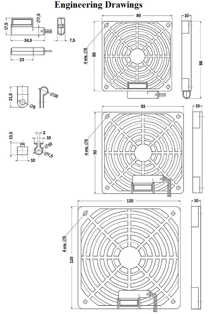
Information about a sensor plugin is in the document “User Guide” for a device, to which you connect a sensor. Information about configuring a sensor and its functionality is in the document “Firmware Description” for a device, to which you connect a sensor.
A sensor is packaged with an inseparable cable, with connectors on the ends. A cable length can be increased with the help of flat cable extenders of RC-4 sensor, which are sequentially plugged one into another. Or it can be done independently with the help of any wire with a minimum cross section of 0,4 mm2. Maximum allowable length of a flat cable is 100 m.
Precautionary measures
- It is not allowed to use the air flow sensor in the magnetic field, as in this case the permanent magnet built into the device can involuntarily deviate from its normal position regardless of the air flow.
- The sensor should be placed at a sufficiently large distance from electromagnetic fields, for example, created by transformers, powerful engines and so on, since otherwise the contact can switch with the frequency of the electromagnetic field. The interference must be checked with an oscilloscope and, if necessary, you should change the mounting location.
- Avoid mounting points where there are formations of air cushions or airflow swirls.
- It is not allowed to use the sensor in case of high dust content in the environment.
- The switched power should not exceed 10 Watts.
- Short-term excess of maximum voltage and maximum current is not allowed.
- For inductive or capacitive loads, the resulting starting voltages and currents must be limited by a suitable protective circuit.
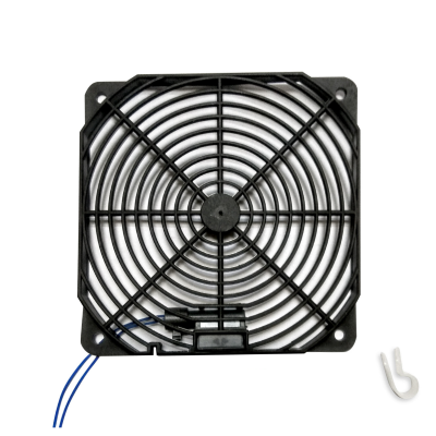
 Cable 4 extender, 4m
  NetPing 2 IP PDU ETH 53R14
 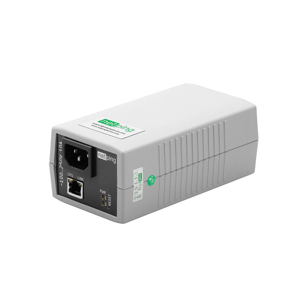 NetPing 2 IP PDU ETH R2
  NetPing 2 IP PDU GSM3G 203R15
 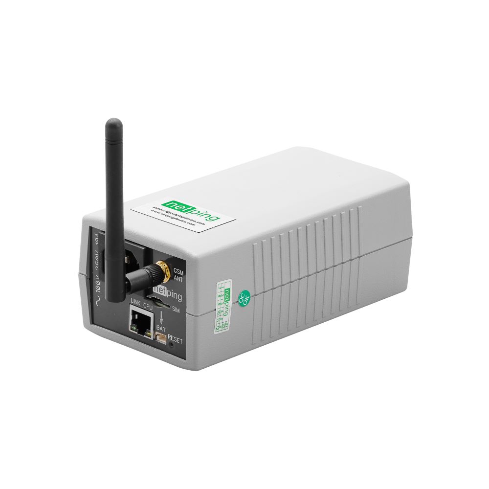 NetPing 2 IP PDU GSM3G R2
  NetPing 4 IP PDU ETH R8
 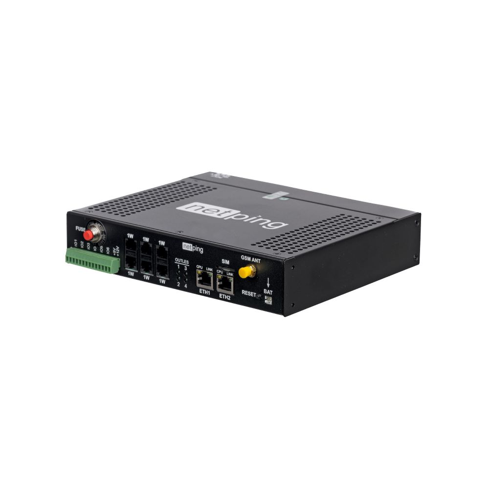 NetPing 4 IP PDU GSM3G 64R701
  NetPing 4 IP PDU GSM3G 64R702
  NetPing 4 IP PDU GSM3G R8
  NetPing 8 IP PDU ETH R8
  NetPing 8 IP PDU ETH R9
  NetPing 8 IP PDU GSM3G R9
 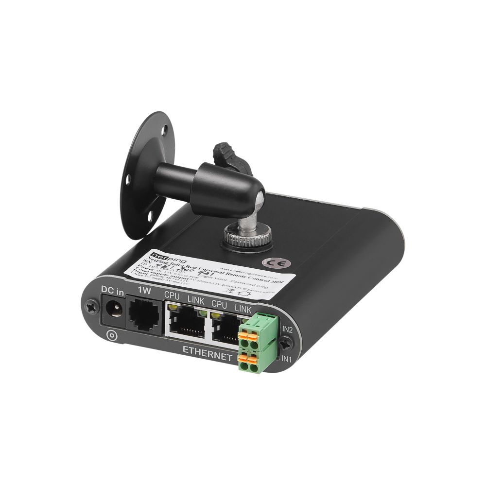 NetPing Infra Red Universal Remote Control 3802
 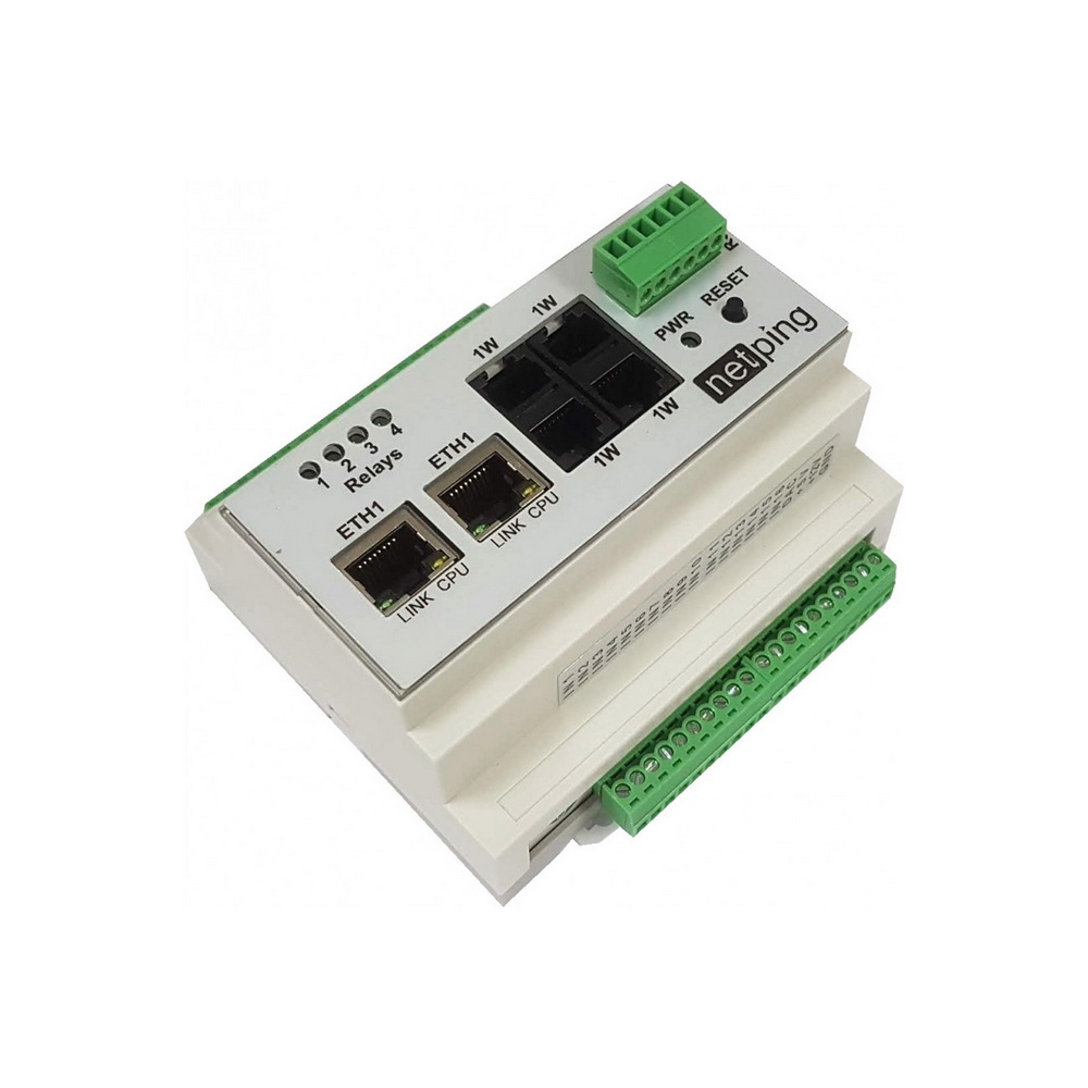 NetPing Input+Relay R404
 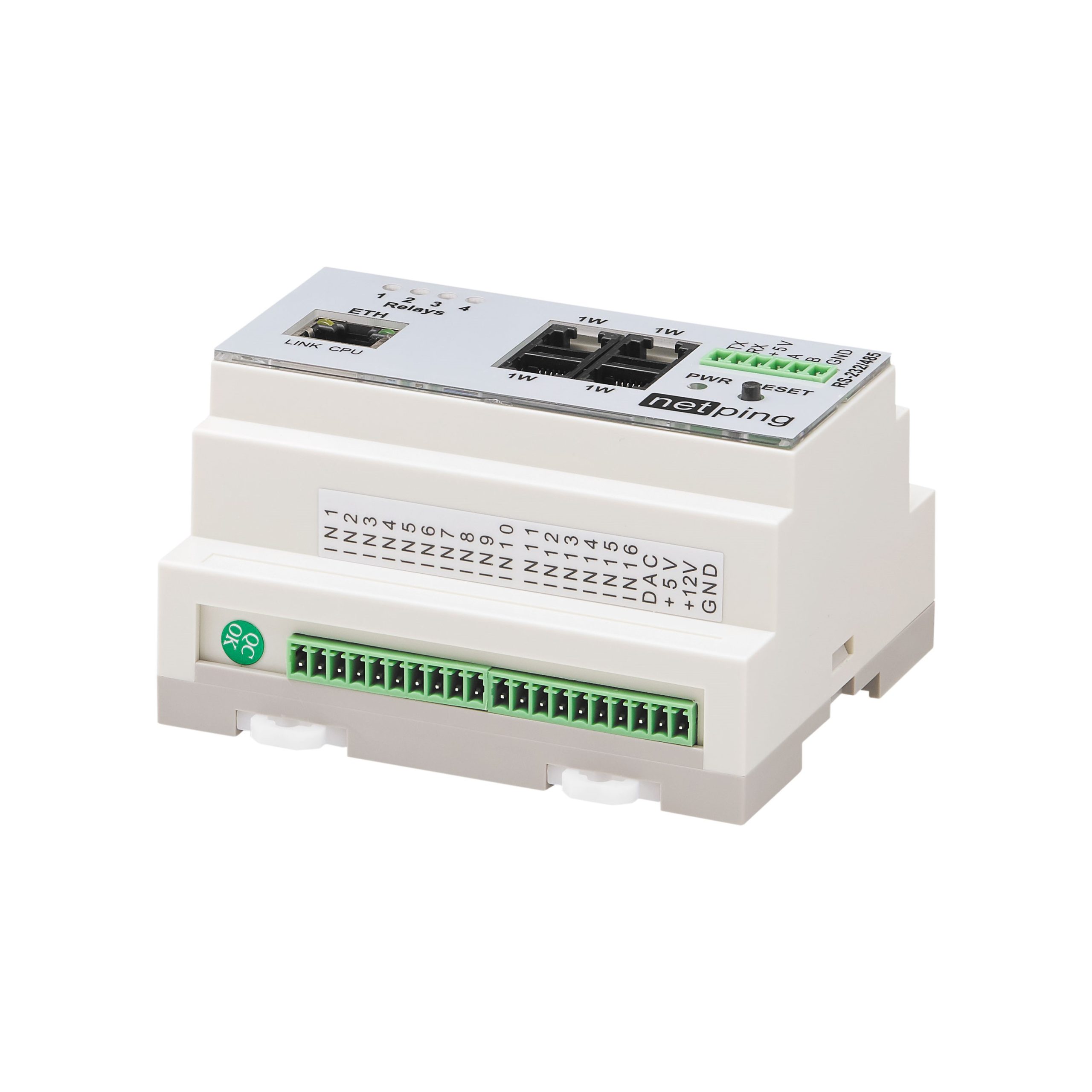 NetPing Input+Relay R504
  NetPing Input+Relay R604
  NetPing Input+Relay R704
 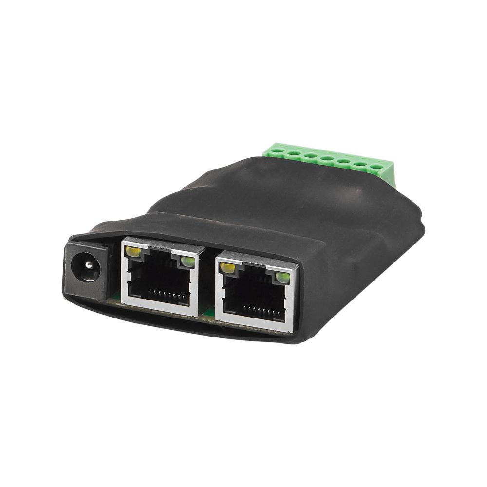 NetPing IO R401
  NetPing Monitor M1
  NetPing Monitoring Solution GSM3G R61
  NetPing Monitoring Solution R61